Mobile Exploration Robot with Auxiliary Drone
ROS2, Embedded Systems, Multi-Robot System, Autonomous Flight
Overview
Terraflight is a ROS2-controlled mobile exploration robot built from the ground up. The custom-built rover carries a drone that can be deployed from the field during operation.
The robot streams live video from both the rover and drone, and also uses a LiDAR module to perform SLAM and map its environment. The entire system is controlled and monitored from a base station.
The drone is primarily teleoperated, but is able to autonomously re-land on the rover. The drone localizes the rover with AprilTags, after which the user is able to call the autonomous landing service with the joystick controller.
GitHub Source Code: https://github.com/henryburon/terra-flight
Contents
Structure
The robot is built with a Raspberry Pi 4 and is fully controlled using ROS2 in Python.
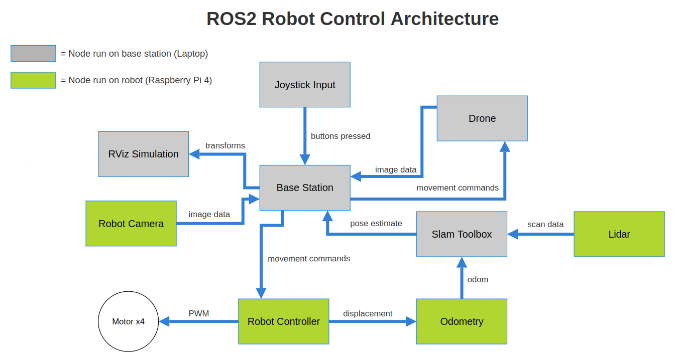 Figure 1. Block diagram representing a simplified view of the robot’s control and communication architecture within the ROS2 framework.
Due to the computational limitations of the onboard Raspberry Pi 4, which functions as the robot’s central processing unit, the architecture is designed to delegate computation and data processing to the base station and reduce the Pi’s overall processing responsibilities when that is not possible. This necessity accounts for the low frequency of the robot’s camera feed (2 Hz).
View the source code for more information on the ROS2 packages that make up this project.
Features
Drone
The rover carries a DJI Tello drone on its top platform throughout operation, and is capable of remotely deploying it from the field. The drone is teleoperated via joystick commands from the user, but is capable of autonomously re-landing on the rover after it locates the rover during flight.
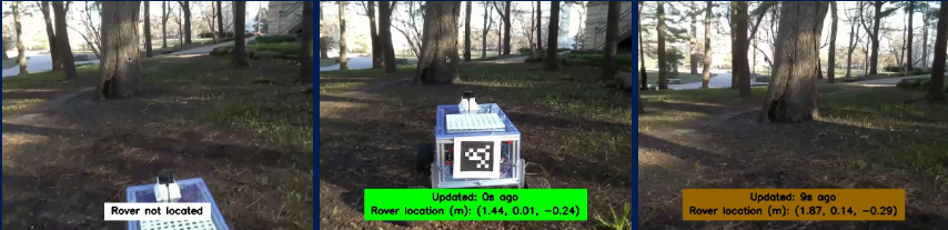
Figure 2. Drone camera feed as it locates the rover.
The drone uses AprilTags on the right, left, and back of the chassis to localize the rover. Once spotted, the user is able to call the autonomous landing service which directs the drone to follow the most recent transform between itself and the rover, adjusting for the location of the specific tag it saw. The drone also displays the time since the last reading, and the update status bar trends towards red as the drone goes longer without an update.
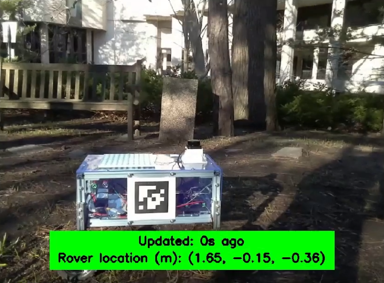
Figure 3. Drone locating the rover via the right tag.
The rover can be located from any of its three AprilTags, and the drone adjusts its autonomous re-landing flight plan to ensure it lands on the rover facing forward.
SLAM
The robot uses a LiDAR module mounted on the top of the rover to perform 2D SLAM and estimate its pose as it creates a map of the environment.
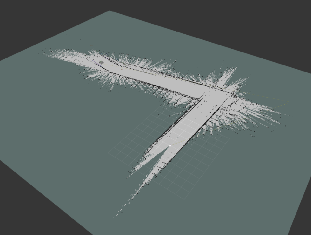
Figure 4. Map created in a hallway at Northwestern’s Tech Institute.
The robot uses SLAM Toolbox. The odometry tf frame is calculated based on wheel velocities.
Base Station
The base station, operated via joystick inputs, is the primary control hub issuing movement commands and processing incoming data. It provides a dynamic interface that offers real-time video stream from the rover and drone, while simultaneously showing the map being built as the robot navigates and explores its environment.
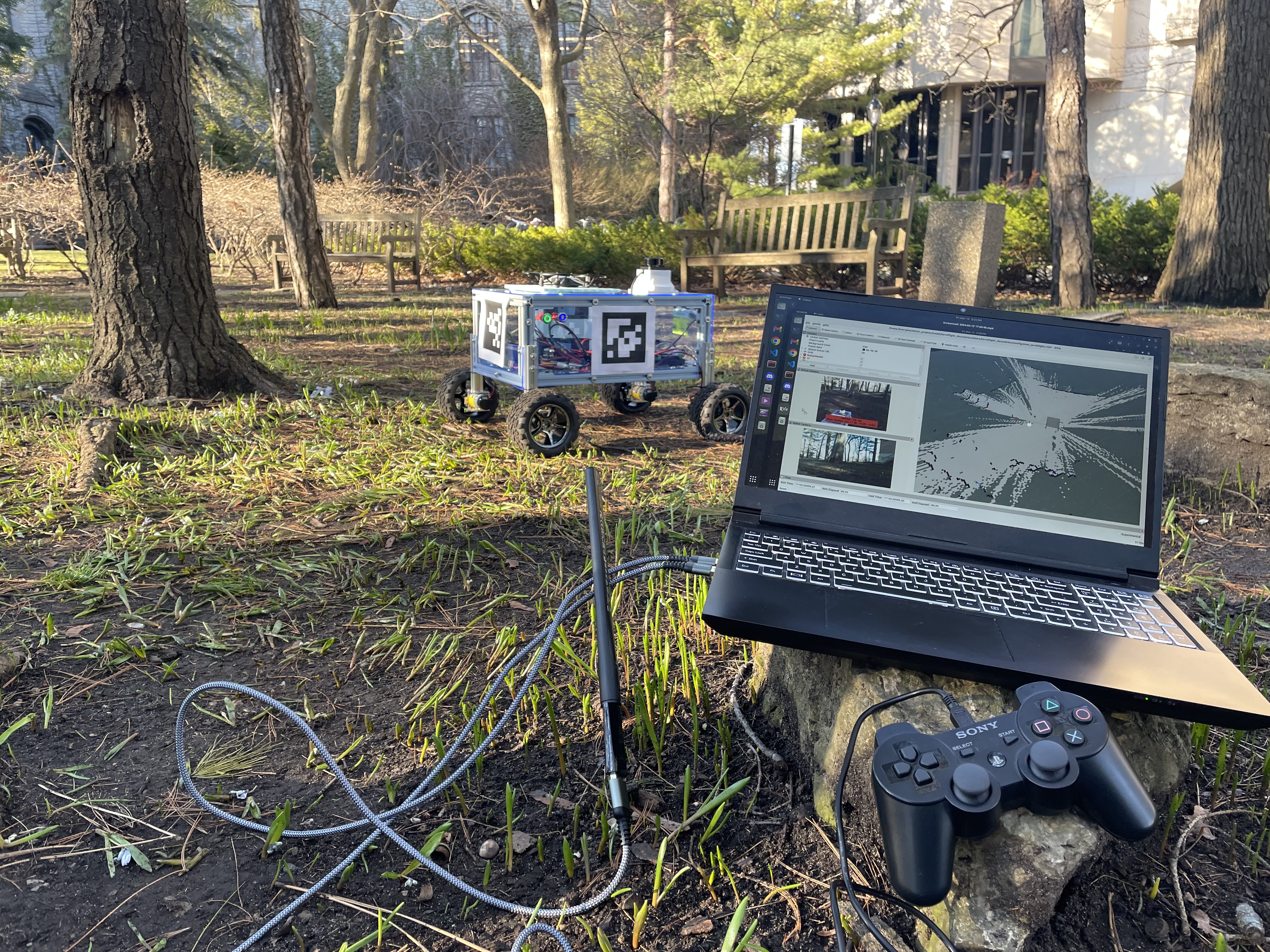
Figure 5. The base station during operation. Hardware includes a laptop, USB WiFi adapter, and joystick controller.
As long as the base station is connected to both the Tello drone’s WiFi network and a network configured to facilitate ROS2 discovery, the robot can be operated anywhere.
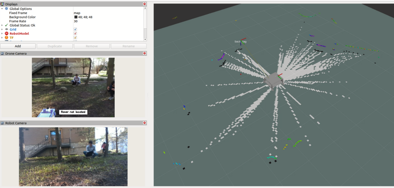
Figure 6. Screenshot from the base station’s interface. Top left: Drone camera. Bottom left: Rover camera. Right: SLAM.
Design
Terraflight was built from scratch.
Electrical
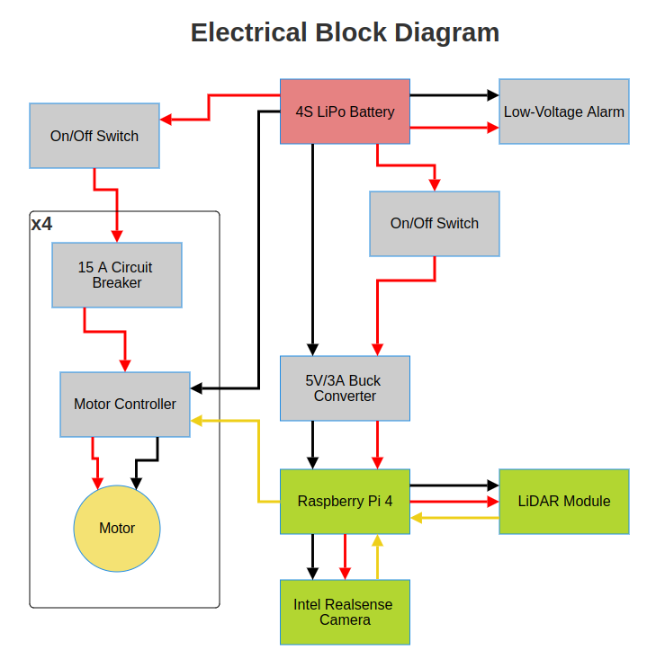
Figure 7. Electrical block diagram.
14.8V main bus. The power system allows the user to power the Raspberry Pi 4 individually when providing software updates.
Mechanical
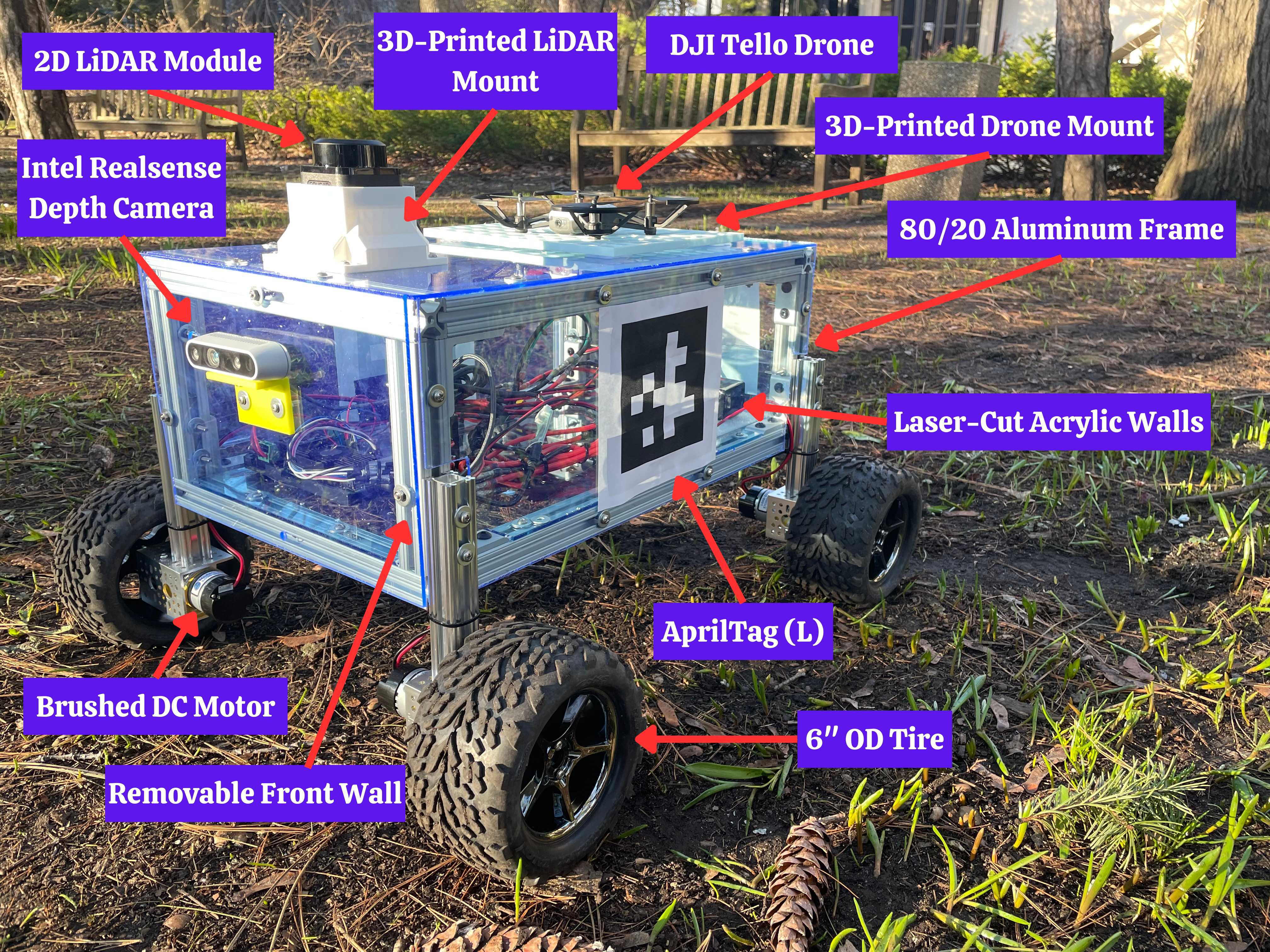
Figure 8. Labeled image of Terraflight.
The rover’s drive train was inspired by NASA’s Open Source JPL Rover.